RS485 Setup for 1696, 1697, and 1698 Power Supplies
2020-01-15
The 1696, 1697, and 1698 comes with a RS-485 terminal in the rear panel that allows users to control multiple power supplies in the same series (up to 31 supplies) through one serial port connection. To do this, users need to have the following:
- 1x ATR-2485 - This is the RS232 to RS485 adapter that can be purchased as an optional accessory from B&K Precision. Contact us for ordering information, or use our "where to buy" tool on our website to find where you can purchase it.
- 1x RS-485 3pin terminal connector / per every power supply that will be connected together (included in original packaging)
- 2x 120 ohm resistors (One is included in original packaging)
Setup connecting wires
- Connect the ATR-2485 adapter to the serial port of the PC that will control all of these power supplies.
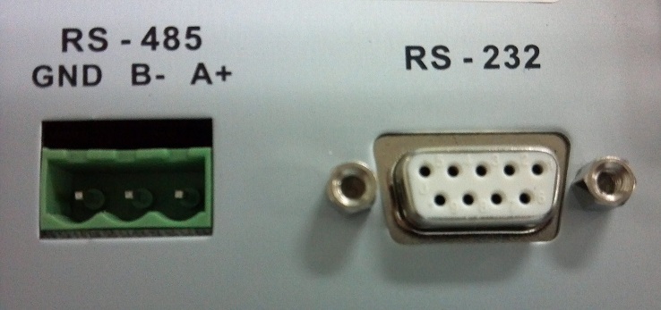
- RS-485 protocol requires three wires that are daisy chained in parallel with all power supplies that will be controlled. Every 1696, 1697, or 1698 power supplies have a 3-pin RS-485 terminal labeled in the rear panel, as shown in the image below.
The 1696, 1697, and 1698 comes with a RS-485 terminal in the rear panel that allows users to control multiple power supplies in the same series (up to 31 supplies) through one serial port connection. To do this, users need to have the following:
- 1x ATR-2485 - This is the RS232 to RS485 adapter that can be purchased as an optional accessory from B&K Precision. Contact us for ordering information, or use our "where to buy" tool on our website to find where you can purchase it.
- 1x RS-485 3pin terminal connector / per every power supply that will be connected together (included in original packaging)
- 2x 120 ohm resistors (One is included in original packaging)
Setup connecting wires
- Connect the ATR-2485 adapter to the serial port of the PC that will control all of these power supplies.
- RS-485 protocol requires three wires that are daisy chained in parallel with all power supplies that will be controlled. Every 1696, 1697, or 1698 power supplies have a 3-pin RS-485 terminal labeled in the rear panel, as shown in the image below.
- The pin labels are as indicated in the image above. A and B are for transmitting and receiving information, while ground (GND) is for reference to ground.
- For each power supply to be connected, attach the 3-pin (green color) connector that fits into the terminals illustrated in the image above.
- Connect 3 wires from the first power supply (pin A, B, and GND) to the 3 pins of the adapter that's already connected to the PC.
- Now, with one 120 ohm resistor, between the A and B that are connected between the first power supplie's A and B pins to the PC's A and B pins.
- Likewise, connect another 120 ohm resistor between the A and B pins of the very last power supply in the connection chain that's connected to the PC's ATR-2485 adapter.
- The connection and wiring for all power supplies should look like the image below:
Setup Address
- Now, power on all of the power supplies. The supplies each need to be assigned with a specific address so that when sending protocols, it will control the specified power supply based on its address.
- Starting with the very first power supply, press "SHIFT" and "RS-232/485" quickly after.
- The display will have RS232 and RS485, with 3 horizontal lines next to RS-232 by default. These lines indicate that RS-232 option is selected.
- Press the RS-232/485 key once to select RS-485 (the 3 lines will be to the left of the "RS485" on display. You will notice that a 3 digit number will show up right below "RS485". This number indicates the address of the power supply.
- Because up to 31 power supplies can be connected in RS485 configuration, this address can be set from between 000 - 031. Use the up or down arrow keys to change. You may find that a number beyond 031 may be selected, but it may not link properly if set beyond 031.
- For easy reference, set this power supply with address of 001 to indicate the first power supply. Once set, press the "ENTER" key to save the changes.
- Do the same for each of the power supplies in the connection chain, making sure that each of them have a unique address different than the other power supplies.
Controlling multiple power supplies
- Once all the power supplies are setup, users may use the SDP software by selecting "Multi" under "Supply Connect" menu. To control each power supplies, use the assigned address that is setup above to select and control accordingly.
- If you are developing your own software application, you will see that the command protocols all have 2 characters that are used to specify address. While this is not used in RS-232 configuration, it is used for RS-485 setup. When sending commands, the address indicated in the command will control the power supply that's been assigned with the same address. For example, SESS04 will control and enable remote mode for power supply with address set to 4.
Related Articles
Featured Products:
1696
Programmable DC Power Supply, 1-20VDC, 0-9.99A