Measuring Reactive Devices with the 5492C and 5493C Multimeters
2025-06-03
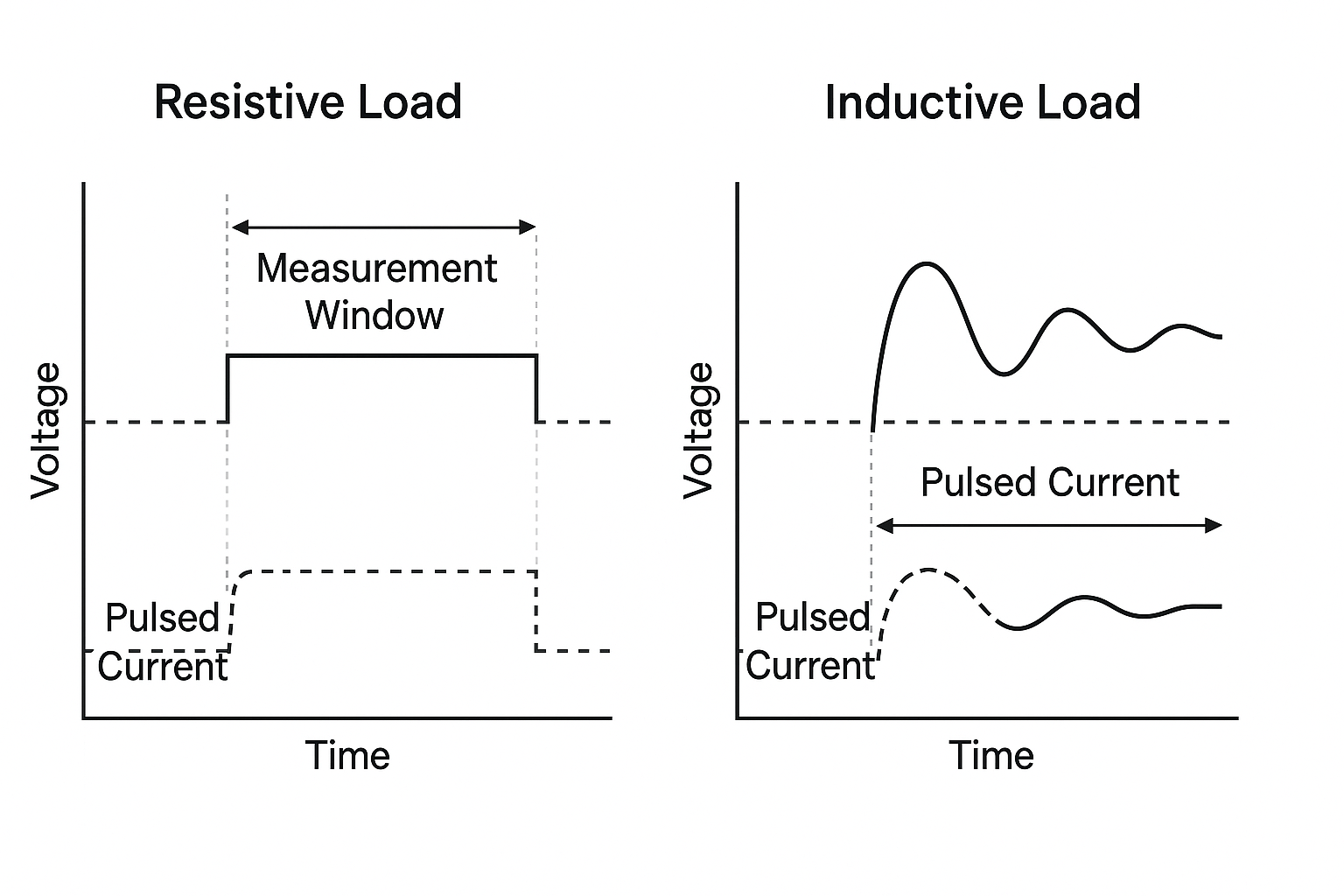
For low-resistance measurements, the 5492C and 5493C multimeters use a pulsed constant current source. This technique helps minimize thermoelectric voltages and leakage currents, which can otherwise introduce errors. Pulsed current measurement is especially accurate when measuring purely resistive loads. When using higher ranges of 1k or higher should prevent the issue with measurements.
However, issues arise when the device under test (DUT) is reactive, meaning it has inductive or capacitive characteristics. Common examples include:
- Inductive: Coils, transformers, relays
- Capacitive: Ceramic capacitors, filter circuits, long cables
In these cases, the pulsed signal used by the multimeter can cause oscillations in the circuit. These oscillations interfere with the settling time of the signal, potentially resulting in an inaccurate resistance reading.
 Note that when long test leads are used to connect the multimeter to the load, the test leads have inherent reactive properties that increase with their length. Only increasing the range to 1k or higher addresses the issue.
When using longer test leads, the additional length adds inductance and capacitance, even if the leads are not coiled. These parasitic reactive elements can affect resistance measurements, particularly with low-resistance or high-frequency signals. As an example: for every meter of lead length can add around 1 µH of inductance that can noticeably delay current rise time during the multimeter’s pulsed measurement and any capacitance between leads (especially if they’re routed close together) can briefly store and discharge charge, further distorting the voltage response.
Here are a few best practices to improve measurement accuracy when dealing with reactive devices or long test leads:
- Use 4-wire (Kelvin) measurements to eliminate lead resistance from the readings.
- Minimize lead length and avoid coiling cables, which increases inductance.
- Use shielded or twisted-pair leads to reduce parasitic capacitance and external noise.
- Enable averaging or slower integration times on the multimeter, if available, to let the signal settle.
- Use null/zeroing features on the meter to cancel out the lead resistance before measurement.
Featured Products:
5492C
5 1/2 Bench Digital Multimeter
5492CGPIB
5 1/2 Bench Digital Multimeter with GPIB
5493C
6 1/2 Bench Digital Multimeter
5493CGPIB
6 1/2 Bench Digital Multimeter with GPIB