Powering Inductive Loads with DC Power Supply
2025-05-22
Introduction
DC power supplies are one of the most standard and widely used test instrument in industrial, R&D, and troubleshooting electronics environments. Applications vary from testing and charging batteries, powering prototype PC boards, sourcing a digital/logic signal, powering motors, relays, transformers, and electromagnets. DC power supplies connected to a device under test (DUT) usually simulate a resistive load, capacitive load, or an inductive load. Connecting a DC power supply to a resistive load circuit or DUT is may be straight forward. However connecting it to an inductive load might not be as simple as it may pose potential problems. In this article, we will focus on some of the inherent challenges of using a DC power supply to source inductive loads and solutions to overcome them.
What is an inductive load?
An inductive load refers to any load in a circuit that has the properties of an inductor. This can be represented as a loop of wire that creates an electromagnetic field when current passes through it. In turn, this field can be used to store energy. It can be measured as an amount of electromotive force (EMF), or a potential, that is generated per a change in current. The mathematical relationship is represented by the formula:
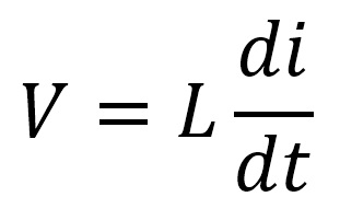
Where V is the voltage generated from a source seen across the inductor, L as the inductance, and i as the current passing through the inductor. A circuit with an inductive load connected to a source can be illustrated below:
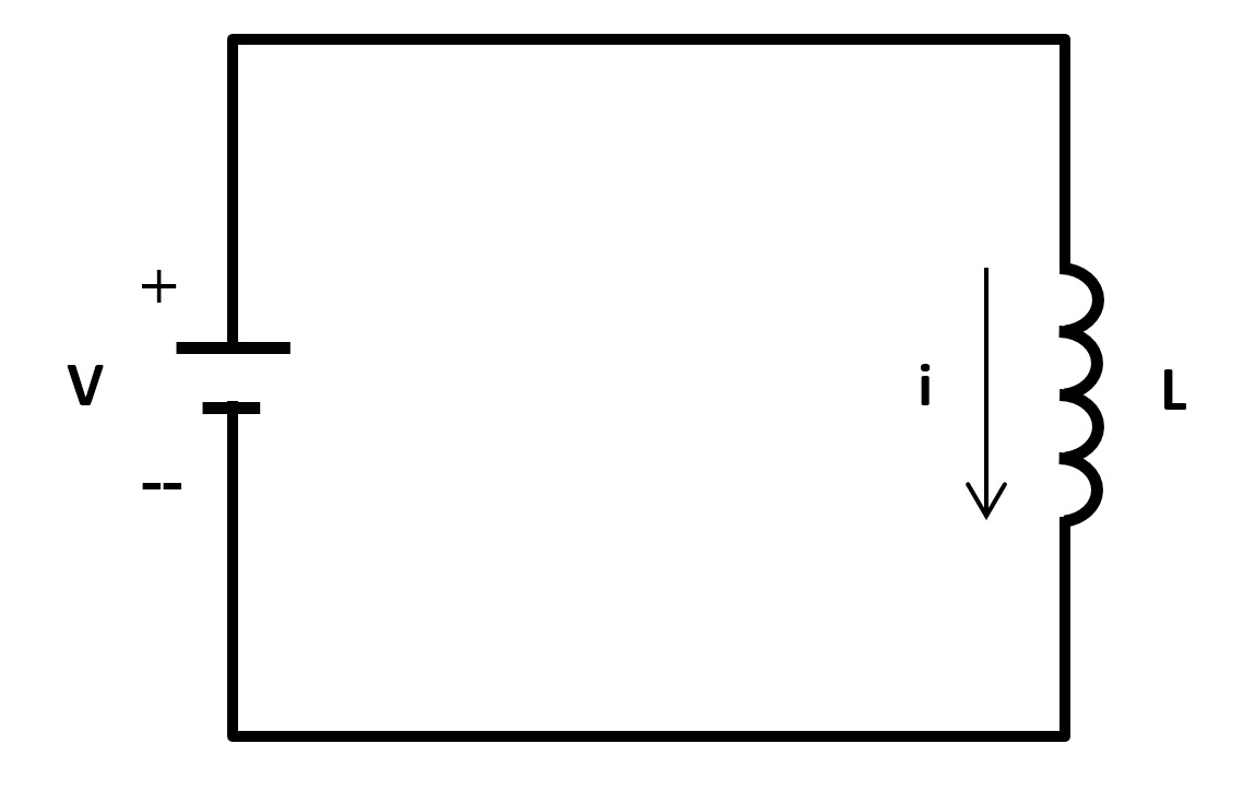
Virtually any circuits or devices that contain wire coils can be classified as inductive. The most common types of inductive loads include electric motors, relays and switches, and transformers.
Problems with inductive loads
One of the most common problems when using a DC power supply to drive an inductive load is the potential feedback that may transmit through the wires connecting to the power supply, thus feeding back voltage into the output of the supply. This feedback, sometimes called a fly-back, can be a large transient, and under certain conditions may impair or damage the DC power supply.
Consider the circuit below:
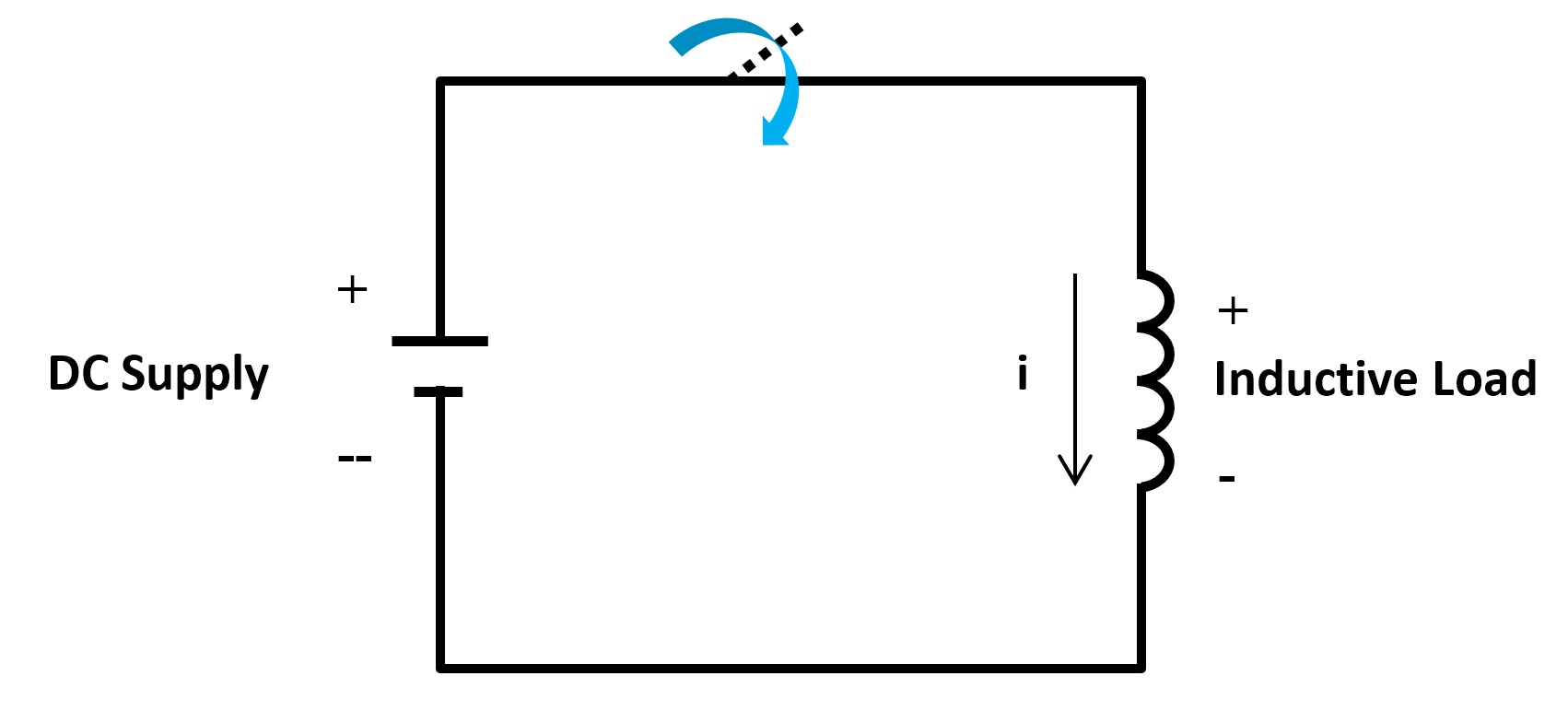
A DC power supply is connected to an inductive load through a switch, and the switch is in the closed position. Current is flowing through from the positive to the negative terminal of the power supply. As current is passing through the inductive load, the inductive coils build up a magnetic field and store energy.
The problem of a fly-back occurs when there is an interruption to the circuit. We illustrate this by opening the switch of the previous circuit, as illustrated below:
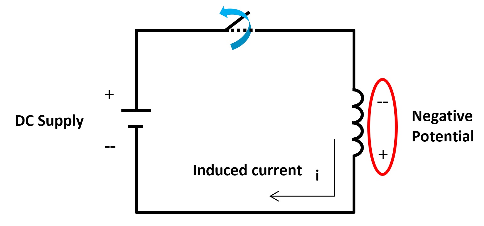
When the circuit is suddenly disconnected from the supply via the switch, current gets interrupted, and in turn changes the magnetic field induced in the inductive load. As this happens, an induced current from the changes in magnetic field will flow in the opposite direction. This is in accordance to Lenz’s law, which states that an electrical current that is induced by a changing magnetic field always creates a counterforce opposing the force that’s inducing it. This is described by the formula:

Where ε is the induced EMF , (∂Φ_B)/∂t is the change in magnetic flux over time, and N is the number of coils in the inductor. The negative sign indicates the change in polarity and direction of current, whose magnetic field opposes the change which created it.
Thus, where there was once a positive potential, a negative potential is created. This negative potential is commonly known as fly-back voltage.
Fly-back voltage can potentially cause problems and may even damage a DC power supply if the voltage is high enough. During sudden events such as opening the switch from the previous circuit can cause a transient high voltage spike. The spike voltage level depends on how quickly current is changed in the inductive load; the faster the change, the greater the spike. This relationship is defined by the formula:
If the rate of change in current ( di/dt ) increases, voltage will increase.
Below is an illustration of the fly-back voltage from when the switch is closed to when the switch opens:
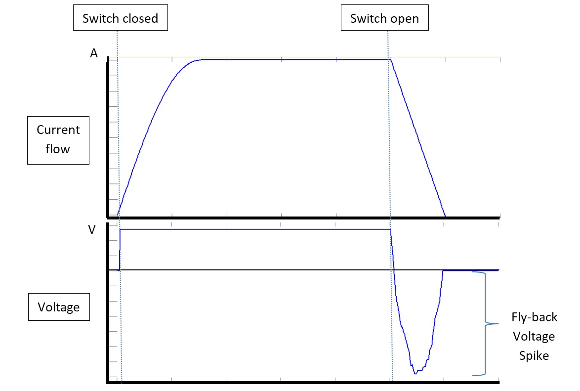
Above, you can see the change in polarity when the switch is opened, as well as the fly-back voltage spike and the reverse direction of current flow. Some of the energy created from this spike may be dissipated within the coils of the inductive load, but a great amount will flow around the circuit. Thus, the spike will be fed back to the power supply’s output terminals and potentially cause damage or electrical interruption to the internal circuits of the supply. The damage or interruption depends on the magnitude of the spike. Some DC power supplies will protect against these anomalies up to a certain threshold voltage level; while some may cause its output to suddenly shut down, restart itself, or trip overload or over voltage protection if available.
Prevent Fly-back Voltage
The most typical and cost effective way to prevent fly-back voltage from damaging your DC power supply is to connect a fly-back diode in parallel to the inductive load you are testing with. The setup may look like the circuit diagram below:
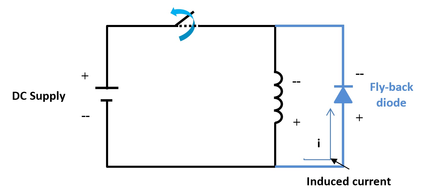
Pay particular attention to the direction of the diode. The direction should be the same as the circuit above in order to prevent it from activating during normal operation. You only want it to conduct the induced current when a fly-back condition occurs. With the above setup, the induced current from the inductive load will flow through the diode and be re-routed back into the load and continuously loop around until the induced energy is completely dissipated through the wires and across the diode.
The diode should be placed within minimal distance from the inductive load. Lengthy wires may radiate unwanted electrical noise which could have an adverse effect to the load or other electrical equipment near it.
Recommended specification for diode
In selecting the appropriate fly-back diode, consider the reverse breakdown voltage (or DC blocking voltage) specification, which needs to be greater than the voltage that is supplying power to the inductive load. In addition, the forward current should be greater than or equal to the maximum induced current that would flow from the inductor.
Disadvantage
While considering a diode to prevent fly-back from damaging your power supply, take into account that the diode will allow a continuous flow of current until energy is dissipated. If your load consists of relays and switches, this flow of current may cause them to actuate a little longer. This must be taken into consideration with the design of the device under test, as it might cause unwanted adverse effects such as decreasing the life of the relay and switch contacts.